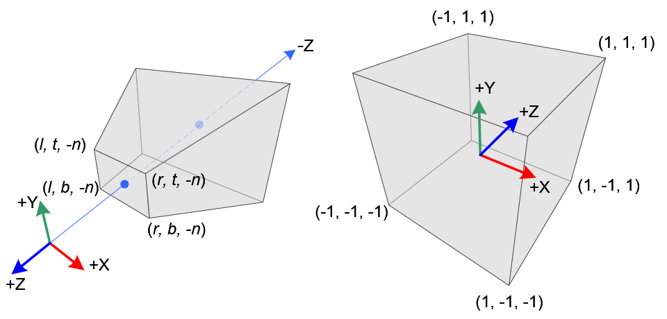
NDC coordinates for OpenGL form a cube, who's -Z side presses against the screen while it's +Z side is farthest away.
I had a look into Song Ho Ahns tutorial about OpenGL transformations to be sure not to tell something silly.
Perspective Projection
In perspective projection, a 3D point in a truncated pyramid frustum (eye coordinates) is mapped to a cube (NDC); the range of x-coordinate from [l, r] to [-1, 1], the y-coordinate from [b, t] to [-1, 1] and the z-coordinate from [-n, -f] to [-1, 1].
Note that the eye coordinates are defined in the right-handed coordinate system, but NDC uses the left-handed coordinate system. That is, the camera at the origin is looking along -Z axis in eye space, but it is looking along +Z axis in NDC.
(Emphasizing is mine.)
He provides the following nice illustration for this:

So, I came to the conclusion that
glm::ortho<float>(-1, 1, -1, 1, -1, 1);
shouldn't produce an identity matrix but instead one where z axis is mirrored, e.g. something like
|  1  0  0  0 |
|  0  1  0  0 |
|  0  0 -1  0 |
|  0  0  0  1 |
As I have no glm at hand, I took the relevant code lines from the source code on github (glm). Digging a while in the source code, I finally found the implementation of glm::ortho() in orthoLH_ZO():
template<typename T>
GLM_FUNC_QUALIFIER mat<4, 4, T, defaultp> orthoLH_ZO(T left, T right, T bottom, T top, T zNear, T zFar)
{
    mat<4, 4, T, defaultp> Result(1);
    Result[0][0] = static_cast<T>(2) / (right - left);
    Result[1][1] = static_cast<T>(2) / (top - bottom);
    Result[2][2] = static_cast<T>(1) / (zFar - zNear);
    Result[3][0] = - (right + left) / (right - left);
    Result[3][1] = - (top + bottom) / (top - bottom);
    Result[3][2] = - zNear / (zFar - zNear);
    return Result;
}
I transformed this code a bit to make the following sample:
#include <iomanip>
#include <iostream>

struct Mat4x4 {
  double values[4][4];
  Mat4x4() { }
  Mat4x4(double val)
  {
    values[0][0] = val; values[0][1] = 0.0; values[0][2] = 0.0; values[0][3] = 0.0;
    values[1][0] = 0.0; values[1][1] = val; values[1][2] = 0.0; values[1][3] = 0.0;
    values[2][0] = 0.0; values[2][1] = 0.0; values[2][2] = val; values[2][3] = 0.0;
    values[3][0] = 0.0; values[3][1] = 0.0; values[3][2] = 0.0; values[3][3] = val;
  }
  double* operator[](unsigned i) { return values[i]; }
  const double* operator[](unsigned i) const { return values[i]; }
};

Mat4x4 ortho(
  double left, double right, double bottom, double top, double zNear, double zFar)
{
  Mat4x4 result(1.0);
  result[0][0] = 2.0 / (right - left);
  result[1][1] = 2.0 / (top - bottom);
  result[2][2] = - 1;
  result[3][0] = - (right + left) / (right - left);
  result[3][1] = - (top + bottom) / (top - bottom);
  return result;
}

std::ostream& operator<<(std::ostream &out, const Mat4x4 &mat)
{
  for (unsigned i = 0; i < 4; ++i) {
    for (unsigned j = 0; j < 4; ++j) {
      out << std::fixed << std::setprecision(3) << std::setw(8) << mat[i][j];
    }
    out << '
';
  }
  return out;
}

int main()
{
  Mat4x4 matO = ortho(-1.0, 1.0, -1.0, 1.0, -1.0, 1.0);
  std::cout << matO;
  return 0;
}
Compiled and started it provides the following output:
   1.000   0.000   0.000   0.000
   0.000   1.000   0.000   0.000
   0.000   0.000  -1.000   0.000
  -0.000  -0.000   0.000   1.000
Live Demo on coliru
Huh! z is scaled with -1 i.e. z values are mirrored on x-y plane (as expected).
Hence, OP's observation is fully correct and reasonable:
...the z component of pos is reflected; -1 becomes 1, 10 becomes -10, etc.
The hardest part:
Why is this?
My personal guess: one of the SGI guru's who invented all this GL stuff did this in her/his wiseness.
Another guess: In eye space, x axis points to right and y axis points up. Translating this into screen coordinates, y axis should point down (as pixels are usually/technically addressed beginning in the upper left corner). So, this introduces another mirrored axis which changes handedness of coordinate system (again).
It's a bit unsatisfying and hence I googled and found this (duplicate?):
SO: Why is the Normalized Device Coordinate system left-handed?


